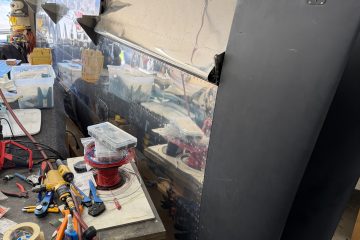
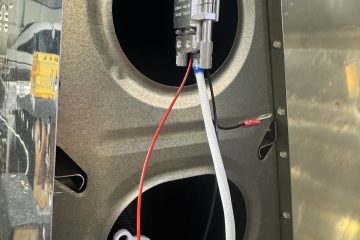
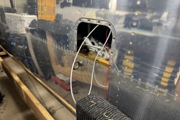
I need to plan the conduits that will traverse the rear seat and baggage area. There isn’t any good way to access that area after I seal it off so I need to get conduit run through that area so I can make runs down the road. In the mean time, I decided to start terminating the wiring in the wings and in the fuselage that I already had planned. I got the pitch trim servo terminated first. The pinout was 1 – White, 2 – Grey, 3 – Orange, 4 – Blue, 5 – Green
I then decided to install the Garmin servo that way I can get the CANBUS wiring going to it and down to the magnetometer.

I then started looking at where to install the magnetometer on the wing tip and one of the criteria is that is must be within 3 degrees of level flight. As such I think I need to do some research to see what level flight is for this wing chord and shape before I just go drilling holes. I think putting it further back on the wing will be best so that I can stay away from the high powered landing and taxi lights.

Finally, since I still had some time in the night I decided to terminate the rear lights for the wing tips. I will need to then terminate the wiring in the wing for the wing tip and add 5 wires that are spliced into the right wires on the main harness to power the rear wingtip lights. I also need to glue in some zip tie mounts in the wing tip so that I can control the wires and they don’t bounce around. I also think I’m going to add some chaffing conduit to the wires going to the rear lights so that they are bundled more easily and saved from any possible chaffing. Plus they’ll just look nicer and more professional. The pinout for the rear light was 1 – Red, 2 – Black, 3 – Blue, 4 – Yellow, 5 – Green


0 Comments